Showing posts with label Wiring. Show all posts

Wiring Diagrams

Bridged
Bridging an amplifier is a means of combining the power of two channels to drive one speaker. Typically this will double the power of a single channel (i.e. two 50 watt channels would combine to become one 100 watt channel) although some of the top amplifiers will actually quadruple the power of a single channel (i.e. two 50 watt channels would combine to become one 200 watt channel). This is usually the most desirable and you can plan this into your overall design. For example, if you have two subwoofers in your system and you want to drive each of them with 100 watts you can do one of the following.


Parallel


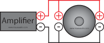
Parallel wiring involves wiring each speaker positive terminal to the positive speaker output of the amplifier and likewise the negative speaker terminals are wired to the negative speaker output of the amplifier.


Series
Series wiring involves connecting the amplifier's positive terminal to the positive terminal of the first speaker and then connecting the negative terminal of the first speaker to the positive terminal of the second speaker and so on. The final speaker in the chain will have its negative terminal connected to the negative terminal of the amplifier. See the figure below. This wiring scheme is best reserved for multiple subwoofers because any audio artifacts (distortion, frequency attenuation, etc.) caused by the first speaker(s) in the chain will affect the speakers in the chain after it. This is a major problem when mixing multiple speaker types (i.e. woofers with tweeters).


Capacitors


There is often a lot of confusion on how to wire a car audio capacitor (a.k.a. power capacitor or stiffening capacitor). There are two terminals on a car audio capacitor. A positive and a negative. The negative terminal is connected to ground. The positive terminal is connected "in-line" with the car audio amplifier +12 volts terminal. See the diagram below.

Ideally the power capacitor should be as close as possible to the amplifier. Within a couple of feet is acceptable.


Charging


Here's how to wire two capacitors in a system:


NOTE OF CAUTION: Power capacitors store a large amount of energy and they charge very quickly. You must first "charge" your power capacitor using a resistor before connecting it directly to +12 volts. This is done with the a 1k ohm resistor and a voltmeter. The exact value of the resistor is not critical but I would keep it in the 500-1k ohm range. I would recommend getting a 1 watt resistor if possible (your capacitor may have come with a resistor for charging). A lower wattage resistor will heat up too quickly. Also, do not hold the resistor with your bare hand. The current flowing through the resistor will cause the resistor to heat up and you could be burned. A good place to put the resistor is in the main power wire fuse holder. Simply substitute the resistor for the fuse. A diagram for the capacitor charging setup is shown below. You will need to place a voltmeter across the capacitor to monitor the voltage. Once the voltmeter reads 12 volts you can remove the voltmeter and replace the resistor with the power fuse.
Click Here to Read More..

Pioneer Video Bypass

Since the high demand for the Pioneer parking brake bypass; I have decided to come up with a easy diagram for you to follow which will allow you to play videos while you are in motion.

1.  Connect the blue system turn on (Remote) wire to spade #85 (If you have or installing and amplifier connect your amplifier turn on (Remote) wire to this prong also)

2. Connect a grounding wire to spade # 87 which jumps and connects to spade # 86. Then connect the wire to a good ground.

3. Connect the parking brake wire from the head unit (Green Wire) to spade # 30

4. Finish installing your stereo and enjoy your video.


Click Here to Read More..

Dual Battery Wiring


WIRE 1

This POS+ wire connects the two batteries' positive posts. This wire allows the rear battery to receive the charge from the alternator, just like the front battery receives. Without this wire, the rear battery would not maintain a charge.

WIRE 1 should be at least 1/0 awg wire. The reason why is that when batteries are connected together, they will instantly equalize in voltage. This can be hundreds of amps of current that is passed. Anything smaller than 1/0 awg wire is likely to be too small to transfer these high currents.

If you intend on pulling more than 300A of current across WIRE 1, you should add an additional run of 1/0 awg for each additional 300A of current you intend on pulling. So if you plan on pulling 600A, you would need two runs of 1/0 awg minimum. The more runs of 1/0 awg you have, the less voltage you can expect to lose due to resistance.

WIRE 2

This POS+ wire connects your amp(s) to your rear battery. This wire should be sized based on the input of your amp(s). If your amp has a 4 awg input, this should be a 4 awg wire. If your amp accepts 1/0 wire, then this should be a 1/0 awg wire.

If you decide that it is better for your setup, you can choose to use a distribution block between the battery's POS+ post and the amps' POS+ inputs. Some people prefer to use a distro block, but it is easier in my mind to simply run the wire directly from the POS+ post to each amp, in effect using the battery as the distro block. There is no right or wrong here, it is up to you to decide.

WIRE 3

This NEG- wire connects the two batteries' negative posts. This wire size should be identical to the size (and quantity) of WIRE 1. So, if you have two runs of 1/0 awg being used for WIRE 1, then you will need two runs of 1/0 awg for WIRE 3 as well.

Some people will argue that using the chassis instead of wire for your NEG- (grounds) connections is fine, but when you have multiple batteries, that is no longer going to be sufficient in most cases. If your car does not have one solid piece of steel running the length of the car, then you will have multiple pieces of steel that are welded together. Steel, as you well know, is a poor conductor when compared to copper (or other highly conductive metals). The conductivity of steel is highly reduced when welded together with another piece of steel. Imagine the weld as a speed bump.

Now the other issue here that is frequently overlooked is that as you begin to draw more current over a conductor, the impedance will actually rise. So simply measuring the resistance of your chassis without a current draw is pointless.

WIRE 4

This NEG- wire is to connect the NEG- connections on your amp to the NEG- post of the rear battery. It is important that this wire matches the size (and quantity) of WIRE 2. Again, just like with WIRE 2, the size of this wire should be determined by your amps' inputs.

Some people again would tell you to not wire this to the battery, but instead to the chassis. This would be OK if you did not have a rear battery and you had a very small amp. But since this discussion is assuming the rear battery is installed, you need to wire the NEG- connection for the amp directly to the battery.

WIRE 5

These wires are to ground each battery to the chassis for devices that may not have a NEG- wire running directly, but are still pulling power from the battery. A good example would be lights or other chassis grounded devices.

One last wire that is not shown, but would fall under the WIRE 5 category would be a wire from the front battery NEG- post to the engine block. This in essence would be the NEG- wire to the alternator, since the engine block is electrically connected to the alternator. If your alternator in fact has a NEG- post, of course the wire should connect there and not at the engine block.

------------------------------------------

And now on to the fuses. Each fuse shown above serves a specific purpose. There are some people who live life on the edge and feel they are a waste of money. There are others who claim that they affect voltages in your vehicle. I am neither of these. I like feeling safe and secure knowing that my electrical system is protected by a fuse. These fuses will not only protect you from improper wiring, but also protect you in case of an accident that shorts out a POS+ wire. Also, good ANL fuses have very little added resistance, so the voltage drop across a fuse is usually not measurable.

FUSE A

This fuse should be located as close to the POS+ post of the front battery as possible. This fuse should be rated to match the current rating of WIRE 1. If you are using a single run of 1/0 awg wire for WIRE 1 and it is rated up to 300A, then FUSE A should be rated at the same 300A.

What FUSE A does is protect your wire from transferring more current (amps) than it is rated for. In the case of a short circuit in the middle on WIRE 1, the front battery will try to push all of it's energy through WIRE 1 to that short. When this happens, the amount of current will exceed the fuse value and cause the fuse to blow. When the fuse blows, the short is alleviated and no more current will pass along WIRE 1 from the front battery.

If the fuse would not have blown, the excessive amount of current would have exceeded the capacity of WIRE 1, which would have caused a fire.

FUSE B

This fuse does the exact same thing as FUSE A with the exception that it protects WIRE 1 from the current coming from the rear battery. If WIRE 1 were to be shorted, there is a potential for energy to flow from both batteries. A fuse on both ends of WIRE 1 is essential. Again it should be located as close to the POS+ post of the rear battery as possible.

And there is no reason to use only one of these two fuses here on WIRE 1. If you don't have both FUSE A AND FUSE B, then you are not protected from a short. So don't think that having one of the two is going to help you. Unless you have both, you are not protected at all.

FUSE C

This fuse is intended to protect WIRE 2 from to much current. Just as with WIRE 1 and FUSE A & B, you are going to match FUSE C with the current rating of WIRE 2. So if your amp accepts 4 awg wire, WIRE 2 should be 4 awg. If your 4 awg wire is rated up to 125A, then FUSE C should be 125A.
Click Here to Read More..

Quad DVC Subwoofer Wiring


Parallel/Parallel DVC Subwoofer Wiring:


* Four 4 ohm DVC subwoofers = 0.5 ohm amplifier load
* Four 8 ohm DVC subwoofers = 1 ohm amplifier load


Series/Parallel DVC Subwoofer Wiring:


* Four 1 ohm DVC subwoofers = .5 ohm amplifier load
* Four 2 ohm DVC subwoofers = 1 ohm amplifier load
* Four 4 ohm DVC subwoofers = 2 ohm amplifier load
* Four 8 ohm DVC subwoofers = 4 ohm amplifier load


Parallel/Series DVC Subwoofer Wiring:


* Four 1 ohm DVC subwoofers = 2 ohm amplifier load
* Four 2 ohm DVC subwoofers = 4 ohm amplifier load
* Four 4 ohm DVC subwoofers = 8 ohm amplifier load
* Four 8 ohm DVC subwoofers = 16 ohm amplifier load

Click Here to Read More..

Triple DVC Subwoofer Wiring


Parallel/Parallel DVC Subwoofer Wiring:


* Three 4 ohm DVC subwoofers = 0.67 ohm amplifier load
* Three 8 ohm DVC subwoofers = 1.33 ohm amplifier load


Series/Parallel DVC Subwoofer Wiring:


* Three 1 ohm DVC subwoofers = 0.67 ohm amplifier load
* Three 2 ohm DVC subwoofers = 1.34 ohm amplifier load
* Three 4 ohm DVC subwoofers = 2.67 ohm amplifier load
* Three 8 ohm DVC subwoofers = 5.36 ohm amplifier load


Parallel/Series DVC Subwoofer Wiring:


* Three 1 ohm DVC subwoofers = 1.125 ohm amplifier load
* Three 2 ohm DVC subwoofers = 2.18 ohm amplifier load
* Three 4 ohm DVC subwoofers = 2.45 ohm amplifier load
* Three 8 ohm DVC subwoofers = 2.82 ohm amplifier load

Click Here to Read More..

Dual DVC Subwoofer Wiring


Parallel/Parallel DVC Subwoofer Wiring:


* Two 1 ohm DVC subwoofers = 0.25 ohm amplifier load
* Two 2 ohm DVC subwoofers = 0.5 ohm amplifier load
* Two 4 ohm DVC subwoofers = 1 ohm amplifier load
* Two 8 ohm DVC subwoofers = 2 ohm amplifier load


Series/Parallel DVC Subwoofer Wiring:


* Two 1 ohm DVC subwoofers = 1 ohm amplifier load
* Two 2 ohm DVC subwoofers = 2 ohm amplifier load
* Two 4 ohm DVC subwoofers = 4 ohm amplifier load
* Two 8 ohm DVC subwoofers = 8 ohm amplifier load


Parallel/Series DVC Subwoofer Wiring:


* Two 1 ohm DVC subwoofers = 1 ohm amplifier load
* Two 2 ohm DVC subwoofers = 2 ohm amplifier load
* Two 4 ohm DVC subwoofers = 4 ohm amplifier load
* Two 8 ohm DVC subwoofers = 8 ohm amplifier load

Click Here to Read More..

Single DVC Subwoofer wiring


Parallel DVC Subwoofer Wiring:


* One 1 ohm DVC subwoofer = 0.5 ohm amplifier load
* One 2 ohm DVC subwoofer = 1 ohm amplifier load
* One 4 ohm DVC subwoofer = 2 ohm amplifier load
* One 8 ohm DVC subwoofer = 4 ohm amplifier load


Series DVC Subwoofer Wiring:


* One 1 ohm DVC subwoofer = 2 ohm amplifier load
* One 2 ohm DVC subwoofer = 4 ohm amplifier load
* One 4 ohm DVC subwoofer = 8 ohm amplifier load
* One 8 ohm DVC subwoofer = 16 ohm amplifier load

Click Here to Read More..

Quad SVC Subwoofer Wiring


Parallel SVC Subwoofer Wiring:


* Four 2 ohm SVC subwoofers = 0.5 ohm amplifier load
* Four 4 ohm SVC subwoofers = 1 ohm amplifier load
* Four 8 ohm SVC subwoofers = 2 ohm amplifier load


Series SVC Subwoofer Wiring:


* Four 1 ohm SVC subwoofers = 4 ohm amplifier load
* Four 2 ohm SVC subwoofers = 8 ohm amplifier load
* Four 4 ohm SVC subwoofers = 16 ohm amplifier load

Click Here to Read More..

Triple SVC Subwoofer Wiring


Parallel SVC Subwoofer Wiring:


* Three 2 ohm SVC subwoofers = 0.67 ohm amplifier load
* Three 4 ohm SVC subwoofers = 1.33 ohm amplifier load
* Three 8 ohm SVC subwoofers = 2.67 ohm amplifier load


Series SVC Subwoofer Wiring:


* Three 1 ohm SVC subwoofers = 3 ohm amplifier load
* Three 2 ohm SVC subwoofers = 6 ohm amplifier load
* Three 4 ohm SVC subwoofers = 12 ohm amplifier load

Click Here to Read More..

Dual SVC Subwoofer wiring


Parallel SVC Subwoofer Wiring:


* Two 1 ohm SVC subwoofers = 0.5 ohm amplifier load
* Two 2 ohm SVC subwoofers = 1 ohm amplifier load
* Two 4 ohm SVC subwoofers = 2 ohm amplifier load
* Two 8 ohm SVC subwoofers = 4 ohm amplifier load


Series SVC Subwoofer Wiring:


* Two 1 ohm SVC subwoofers = 2 ohm amplifier load
* Two 2 ohm SVC subwoofers = 4 ohm amplifier load
* Two 4 ohm SVC subwoofers = 8 ohm amplifier load
* Two 8 ohm SVC subwoofers = 16 ohm amplifier load

Click Here to Read More..

Single SVC Subwoofer Wiring


SVC Subwoofer Wiring


* One 1 ohm SVC subwoofer = 1 ohm amplifier load
* One 2 ohm SVC subwoofer = 2 ohm amplifier load
* One 4 ohm SVC subwoofer = 4 ohm amplifier load
* One 8 ohm SVC subwoofer = 8 ohm amplifier load

Click Here to Read More..
 
Site Meter